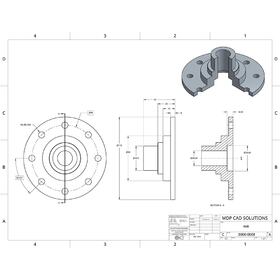

This means that you won’t have to throw away your work and start again. By using software, such as BricsCAD BIM, all your drawings will stay in one file type. Again this leaves plenty of room for error.
#EXAMINE 2D 3D SOFTWARE SOFTWARE#
Sometimes the confusion comes when a design is created in 2D in one piece of software and then converted into 3D in another format. This can create inconsistency and will almost certainly guarantee errors! Using different platforms The problem comes if the 2D views lose their connection to the 3D model. Losing the connection between 2D and 3DĮven if you create a 3D model, in many cases, you will still need to generate 2D drawings at some point in the development process. From augmented reality, to point clouds, the future may well be 3D. However, don’t be so sure! As technology progresses, we are likely to see an increase in the number of construction workers with CAD tools available to them on site. Some people claim that a 3D model is “near useless” when conveying construction or manufacturing instructions to a builder or toolmaker and that 2D plans may better serve this purpose. In addition, CAD offers more capabilities such as light simulations, real-time rendering and parametrically driven design. Many architects still build maquettes, but CAD or BIM models have the advantage: they are much easier to adapt and modify, even at a late stage in the design process. Image credit HOK Architecture and Construction Use simulations to track the movement of the sun throughout the day.

#EXAMINE 2D 3D SOFTWARE FULL#
However, if you’re designing a kitchen, your client might not be to think in 3D and the idea might be more convincing if it’s presented in 3D, with a full render. Will you need to produce 2D drawings so that an electrician can wire the assembly? If so, you might not need the 3D model. Although 3D CAD might be more “fun”, it might not be the clearest way to present your idea. Remember: the purpose of a good CAD drawing is to convey information. Let’s explore 2D vs 3D CAD: What is your end product?īefore you even start drawing, think about your end goal. Although 3D can seem exciting before you jump in ask yourself: is 3D the right choice? For this reason, you might be wondering if it’s time to make the move from 2D to 3D. You continue to build out all the part’s features until the final CAD model is created like the example below.Increasingly, it seems that people are expecting 3D CAD models over 2D drawings. 2D sketches are then converted into 3D features. You want to start the CAD drawing with tracing basic 2D sketches along with creating standard relationships and constraints in order to maximize control over how your design is developed. It’s pretty much tracing right on top of the scan data. 3D scan data serves as a visual guide for sketching the CAD drawing. The scanner typically outputs 3D scan data as dense triangle mesh in obj, ply, or stl mesh formats-anywhere from a few thousand to millions of polygons.Īrmed with this intelligence, you can use it to replicate the part or create a new design based on the original. However, they are often proven limiting when trying to measure complex parts with complicated features (e.g. Calipers and hand tools have traditionally been used to take measurements. The first part of the process involves using a 3D scanner to collect the geometric surface measurements of an existing part quickly and accurately. What does the reverse engineering workflow look like at a glance?
#EXAMINE 2D 3D SOFTWARE HOW TO#
While the concept of reverse engineering is quite simple, most people don’t have a good grasp of the step-by-step workflow on how to create CAD from 3D scan data. The goal is to ultimately create a new CAD model for use in manufacturing. Reverse engineering empowers you to analyze a physical part and explore how it was originally built to replicate, create variations, or improve on the design. Sometimes you don’t have access to a part’s original design documentation from its original production. Reverse Engineering 101: Step-by-Step Guide to Creating Parametric CAD from 3D Scan Data


 0 kommentar(er)
